Calculating Power Budget for Fiber-Optic Cable
To ensure that fiber-optic connections have sufficient power for correct operation, you need to calculate the link's power budget, which is the maximum amount of power it can transmit. The transmitter and the receiver have minimum and maximum values and when you calculate the power budget, you use a worst-case analysis to provide a margin of error, even though all the parts of an actual system do not operate at the worst-case levels. To calculate the worst-case estimate of power budget (PB), you assume minimum transmitter power (PT) and minimum receiver sensitivity (PR):
PB = PT – PR
The table below shows two examples on calculations for power budget and minimum loss required:
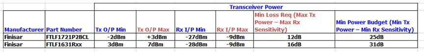
The power budget for the Finisar SFP PN FTLF1721P2BCL is 25dB (-2dB - -27dB = 25dB) which means you can lose up to 25dB in the fiber/connections and it still operate within its specifications. On the other hand, the min loss required is 12dB (3dB - -9dB = 12dB) and this means the signal needs to be attenuated by 12dB to meet the transceiver spec.
For PN FTLF1631Rxx, the power budget is 31dB which means you can lose up to 31dB in the fiber/connections and it still operate within its specifications. The min loss required is 16dB and this means the signal needs to be attenuated by 16dB to meet the transceiver spec.
Calculating Power Margin for Fiber-Optic Cable
After calculating a link's power budget, you can calculate the power margin (PM), which represents the amount of power available after subtracting attenuation or link loss (LL) from the power budget (PB). A worst-case estimate of PM assumes maximum LL:
PM = PB – LL
PM greater than zero indicates that the power budget is sufficient to operate the receiver.
Factors that can cause link loss include higher-order mode losses, modal and chromatic dispersion, connectors, splices, and fiber attenuation. Table 1 lists an estimated amount of loss for the factors used in the following sample calculations. For information about the actual amount of signal loss caused by equipment and other factors, refer to vendor documentation.
Table 1: Estimated Values for Factors Causing Link Loss:

The following sample calculation for an 8-km-long single-mode link with a power budget (PB) of 13 dB uses the estimated values from Table 1 to calculate link loss (LL) as the sum of fiber attenuation (8 km @ 0.5 dB/km, or 4 dB) and loss for seven connectors (0.5 dB per connector, or 3.5 dB). The power margin (PM) is calculated as follows:
PM = PB – LL
PM = 13 dB – 8 km (0.5 dB/km) – 7(0.5 dB)
PM = 13 dB – 4 dB – 3.5 dB
PM = 5.5 dB
The calculated power margin is greater than zero, indicating that the link has sufficient power for transmission and does not exceed the maximum receiver input power.
Sources:
CC HW Engineering