Matrix: How do I wire up the V-Panel logic inputs to a panel switch or foot switch?
Question: How do I wire up the logic inputs on the V-Series panel via the rear panel DB-25 connector to be activated via a remote panel switch or foot switch? How many logic inputs can I access on a V-Series panel?
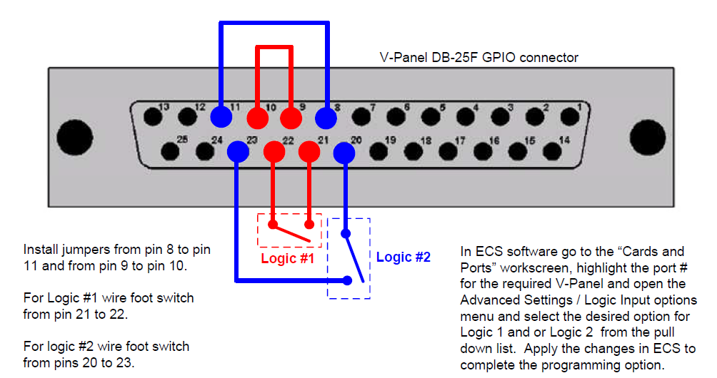
Answer: The chart below will show the logic input 1 and 2 wiring to a panel switch or foot switch to rear panel DB-25F GPIO connector on the V-Panel.
Logic Inputs 1 and 2 are programmable via ECS / EHX software control,
Logic input 3 is hardwired to trigger the "REPLY" key on the V-Panel
Logic input 4 will activate "EXIT SUPERVISOR MODE"
Note: This solution is also attached as a PDF document below.


note : you can also wire the external switch to ground by wiring
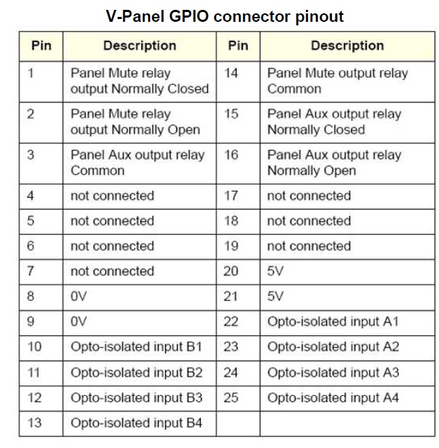
Pin 21 (5V) to Pin 22 (opto input A1)
The external switch to Pin 9 (0V) & Pin 10 (opto input B1)
CAN'T FIND YOUR ANSWER? CLICK HERE TO CONTACT SUPPORT
This solution was provided to you by Clear-Com via a question submitted to us by customers like you. If your question wasn’t answered, you need help or you have a recommended solution for our database, please send us an email at support@clearcom.com
The information on this page is owned by Clear-Com and constitutes Clear-Com’s confidential and proprietary information, may be used solely for purposes related to the furtherance of Clear-Com’ business and shall not be disclosed, distributed, copied or disseminated without Clear-Com’s prior written consent. Click Here for Clear-Com's privacy statement.