The CCI-22 interfaces are connected to the matrix frame through the two RJ-45
connectors on the IMF-3 or IMF-102 rear-panel assembly to which CCI-22 is
connected. For connection to a matrix frame refer to the “Installation in Interface
Frame” on page 2-1. For internal jumper settings and adjustments refer to
“Adjustments” on page 2-8.
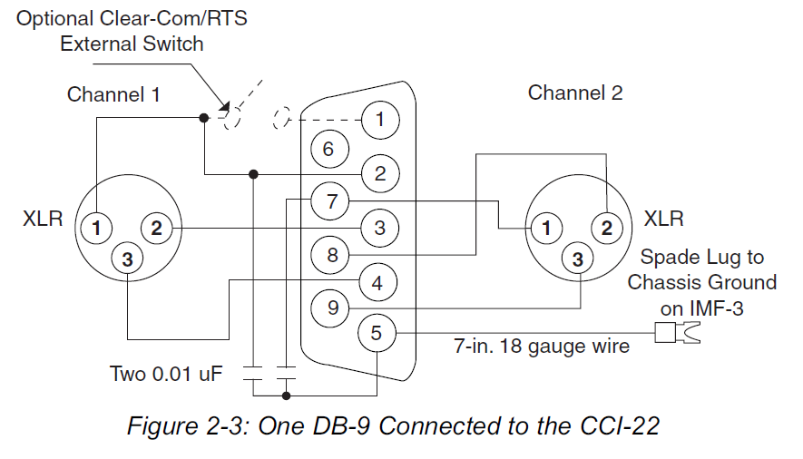
The “user” side of the CCI-22 for each channel is on a pair of DB-9M
connectors on the rear of the interface frame. Figure 2 shows the pinout of either
one of these connectors. Both DB-9Ms are paralleled such that both party-line
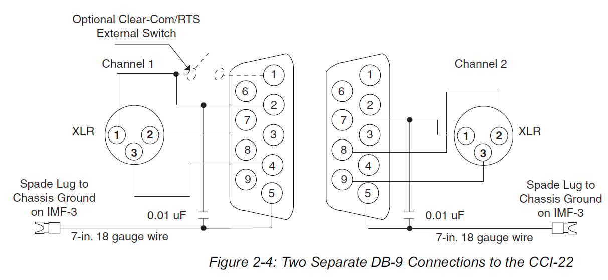
channels are available on each connector. It is possible to wire one DB-9
connector as channel #1, the second DB-9M as channel #2, or bring both
channels out either DB connector separately or create a TW type party-line
connection.
...

MULTIPLE CLEAR-COM BELTPACK CHANNELS FROM
ONE POWER SUPPLY
A single two-output power supply can provide power for more than two
CCI-22 party-line channels. In this case the power supply provides
power for each party-line, but each CCI-22 channel provides the
termination for each party-line. Many Clear-Com power supplies have
a switch to enable or disable the termination circuits from each of its
outputs. If using such a supply:
Disable the terminations by using the switch.
Connect the PS-702 output to all of the CCI-22 channels to be
powered using the standard three connections in the XLR
connector.