...
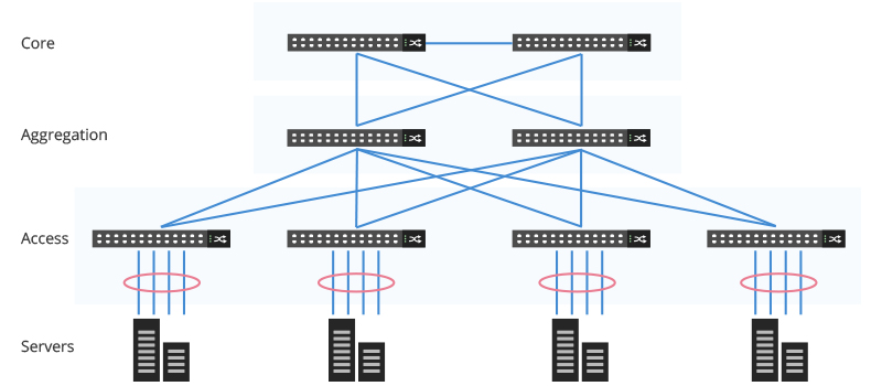
In the past, the majority of data center traffic is from server to server, or from server to storage systems, which we consider as “east to west” traffic. The three-tier architecture model is typically designed for the east to west traffic, so the packet moves through three hops—it flows to the core, is routed to the aggregation layer switch, and then it is forwarded to the access switch where the end devices are connected. With the transformation of data center, it requires more data travel within the data center while the number of hops is increasing, which adds more possibility to packet loss and significant latency. So if running massive east-west traffic through this conventional architecture, devices connected to the same switch port may contend for bandwidth, resulting in poor response time obtained by end-users. Thus, this three-tier architecture is not suitable for the modern virtualized data center where compute and storage servers may be located anywhere within the facility.
...
What Is Spine-leaf Architecture?
With three tier gradually losing momentum in the modern data center, spine-leaf architecture comes to its place. As shown below, the leaf-spine design only consists of two layers: the leaf layer and the spine layer, which reduces the hops and guarantees reduced delay. This is the so-called “leaf-spine” architecture, where there are only two tiers of switches between the servers and the core network.
...
The spine layer is made up of switches that perform routing, working as the backbone of the network. The leaf layer involves an access switch that connects to endpoints like servers, storage devices. In a leaf-spine architecture, every leaf switch is interconnected with each spine switch. With this design, any server can communicate with any other server with no more than one interconnection switch path between any two leaf switches.

Advantages of Leaf-Spine Architecture
...
The figure below illustrates how to measure the oversubscription ratio of leaf and spine layers. The leaf switch has 48× 10G ports, giving a total 480Gb/s of port capacity. If connecting the 4× 40G uplink ports of each leaf switch to the 40G spine switches so the leaf will have a total 160Gb/s uplink capacity. That’s how the ratio comes— 480: 160, and we get the 3:1 ratio.
...

Leaf and Spine Scale — As the endpoints in the network connection only to the leaf switches, the number of leaf switches in the network depends on the interface number required to connect all the endpoints including multihomed endpoints. Because each leaf switch connects to all spines, the port density on the spine switch determines the maximum number of leaf switches in the topology. And the number of spine switches in the network is governed by a combination of the throughput required between the leaf switches, the number of redundant/ECMP (equal-cost multi-path) paths between the leafs, and the port density in the spine switches.
...
| View file | ||
|---|---|---|
|